Heat buildup, overloaded spans, tight bends, and mixed cable groups can turn an apparently neat tray installation into a maintenance and reliability problem. By the end, you will be able to translate a cable schedule into tray dimensions, support details, routing rules, and manufacturer questions that preserve ventilation and cable protection.
Key takeaways
- Verify ampacity using cable count, ambient temperature, spacing, and installation arrangement.
- Size tray width, height, fill, and load from the cable schedule.
- Specify support spacing and attachments to control deflection across the route.
- Check every fitting against the largest cable’s minimum bend radius.
How perforations and cable grouping keep heat from becoming a routing problem
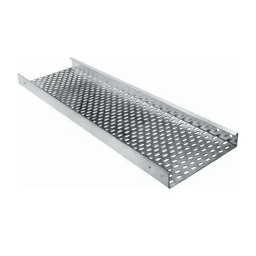
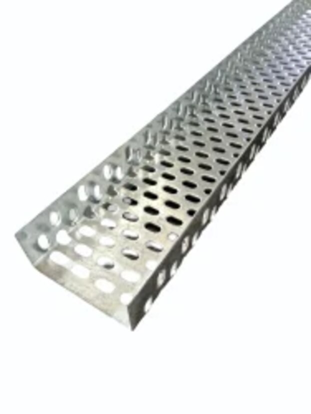
Heat leaves a perforated cable tray through its open sides and base perforations, giving air more paths around cable jackets than a solid-bottom tray. That perforated cable tray ventilation can reduce heat accumulation, but it does not establish ampacity: verify conductor count, loading, ambient temperature, cable construction, spacing, and installation arrangement under the applicable code.
Keep the openings useful by arranging cables in shallow, separated groups rather than pressing one dense bundle across the tray floor:
- Place power cables in their planned group, with control, instrumentation, and communications cables separated by distance, dividers, or separate trays where electromagnetic interference or project rules require it.
- Avoid tightly packed bundles and multiple stacked layers that block air movement and hide the perforations.
- Use ties, clamps, or hold-down hardware at the pattern’s attachment points, and check that small or flexible cables cannot sag through openings.
- Preserve clear access at branch points and drop-outs so cables do not cover every opening.
The tray’s usable area still controls fill; calculate it from the cable schedule instead of judging by visible space. A solid-bottom tray comparison may favour greater protection from falling objects, contamination, ultraviolet exposure, or mechanical damage, while covers and dividers can add protection to a perforated design.
In wet areas, confirm slope, drainage, cover design, corrosion protection, and cable suitability because blocked openings or tightly grouped cables can trap water.
How to size tray width, height, fill, and load from the cable schedule
Select tray dimensions from the cable schedule, not from appearance. Record each cable’s outside diameter, weight per metre, quantity, category, minimum bend radius, and required separation.
1. Group cables by installation rules before adding areas. Keep power cables, control cables, instrumentation, and communications in separate trays or separated compartments when the code or project specification requires it. A single open tray does not create electromagnetic segregation.
2. Perform the cable tray fill calculation using the sum of each cable’s cross-sectional area. Compare that total with the usable interior cross-sectional area of the proposed tray, then apply NEC Article 392.22 for the applicable edition: permitted fill differs for multiconductor cables, single-conductor cables, control cables, and mixed installations.
Add the specified spare capacity rather than treating unused space as automatic reserve.
3. Choose width from the grouped cable layout and separation distances. Choose side-rail height so the planned cable arrangement fits without crushing, excessive stacking, or blocking installation access. Confirm every elbow, tee, reducer, and cross preserves the largest cable’s minimum bend radius; a compliant straight run can still fail at a fitting.
4. Calculate load in kilograms per metre by adding cable weights, tray weight, covers, and accessories. Compare the result with the manufacturer’s working-load rating at the actual support span under NEMA VE 1 or IEC 61537 data.
Do not substitute a concentrated transformer, junction box, or heavy bundle for a uniformly distributed load; add supports or specify stronger construction when required.
How supports and attachments prevent deflection across the route
Choose cable tray support spacing from the installed system’s load and deflection data, not the longest span printed for an empty straight section. Check tray width, cable weight, splice locations, fittings, expansion joints, vibration, wind, and seismic forces; excessive span causes sag, joint stress, and misaligned covers.
Adjust the support plan for each route condition:
- Straight runs: use the manufacturer’s span and working-load table, then verify deflection with the actual cable load. Place supports so every splice is properly supported rather than leaving a joint at mid-span.
- Elbows, tees, crosses, and reducers: add supports near the fitting and at the adjoining straight sections. A fitting changes load distribution, so the straight-run maximum spacing does not automatically apply.
- Vertical sections: anchor the tray to the structure and secure cables with rated cleats or clamps at the intervals specified for their weight and fault forces. Cable ties alone do not restrain a heavy vertical bundle.
- Concentrated loads: support power supplies, junction boxes, transformers, or unusually heavy bundles separately with a support rail, extra hanger, or stronger tray construction. Do not compare a point load with a catalog rating based on uniform loading.
Cantilever brackets suit wall-mounted routes when the wall and anchors carry the reaction. Trapeze supports suspended on threaded rods provide better stability for wider trays and multiple tiers; use locknuts and bracing where movement is possible. Make attachment hardware compatible with corrosion, vibration, and environmental exposure.
How fittings and bend-radius checks preserve cable integrity
Route every transition around the largest cable or bundle entering it, not around the tray’s straight-run dimensions. A run can satisfy fill limits yet damage insulation when a fitting forces a tighter bend than the cable manufacturer’s minimum bend radius.
Check each transition against the cable schedule and manufacturer data:
- Cable tray bends: Select the inside radius from the stiffest or largest cable, then keep that radius continuous through the elbow.
- Tee and cross fittings: Maintain the required radius on the through path and each branch; do not compress cables at the junction.
- Reducers: Keep the cable path gradual, and avoid shifting a full bundle abruptly into the narrower section.
- Vertical rise: Use a radius-controlled riser or drop-out arrangement, with clamps that prevent cables from sliding into a sharp edge.
During pulling, place rollers at straight sections and radius guides through bends. Pulling tension and sidewall pressure can exceed the cable’s installation limits even when the tray’s static load rating is adequate. Stage large power cables in manageable sections instead of dragging a full bundle through several fittings.
Support fittings and vertical transitions separately where their weight or cable movement could stress a joint. Do not apply the longest straight-tray support spacing at every elbow, tee, reducer, or elevation change; excessive deflection can open joints and transfer force into the cables.
Check the finished route for crushed jackets, flattened cable shapes, and unsupported spans before closing covers or connecting equipment.
What to require from a perforated tray manufacturer before approving the layout
Approve the layout only after the manufacturer supplies a dimensioned tray and fitting schedule, not a product photograph. The submission must state allowable load at each proposed support span, based on NEMA VE 1 and IEC 61537 test data; a short-span catalog rating does not validate a longer span.
Request these items:
- Tray width, side-rail height, perforation pattern, minimum supported cable diameter, and usable fill area.
- Elbows, tees, crosses, reducers, and vertical fittings that preserve the largest cable’s minimum bending radius.
- Cable cleats and clamps rated for short-circuit forces, vertical loads, vibration, and seismic movement where those conditions apply.
- Bonding jumpers, earth lugs, and a continuity detail showing how tray sections, fittings, covers, and dividers remain grounded.
- Tray covers and dividers? Require them where falling objects, water, UV exposure, electromagnetic separation, or cable segregation makes open routing unsuitable.
- Material and finish limits for indoor, outdoor, wet, corrosive, high-temperature, or washdown areas, including fastener compatibility.
| Manufacturer evidence | What it confirms | Failure prevented |
|---|---|---|
| Load/span table | Capacity at your actual support spacing | Deflection or collapse |
| Fitting schedule | Bend-radius and usable-capacity compliance | Cable damage at changes in direction |
| Bonding and accessory drawings | Continuous grounding and secure restraint | Shock, movement, or fault-force displacement |
Vickram Engineering can be asked to match its horizontal bends and perforation pattern to the cable schedule, rather than treating fittings and attachment points as afterthoughts. A more open tray improves access and heat dissipation, but it does not establish ampacity or replace code-based cable spacing.
Related products
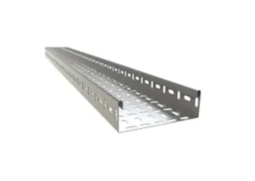
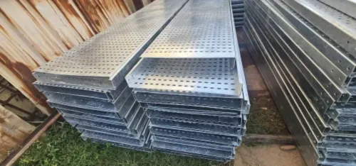
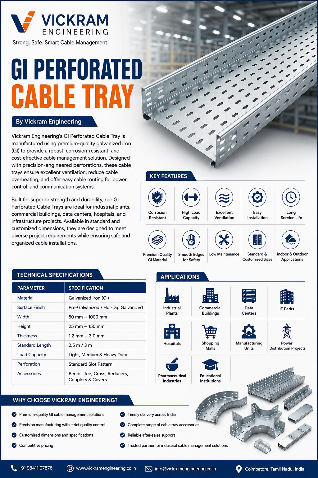 | GI Perforated Cable Tray Vickram Engineering's GI Perforated Cable Tray is manufactured using premium-quality galvanized iron (GI) to provide a robust, corrosion-resistant,... View product → |
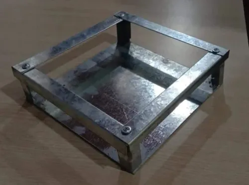
Horizontal Cable Tray Bend Vickram Engineering's Horizontal Cable Tray Bend is a precision-engineered cable management accessory designed to facilitate smooth directional... View product → |
Frequently asked questions
Do perforations establish cable ampacity?
No. Verify conductor count, loading, ambient temperature, cable construction, spacing, and installation arrangement under the applicable code.
How do you size a perforated cable tray?
Use the cable schedule to calculate required width, height, fill, and load, then confirm the selected tray and supports meet those demands.
Why do tray supports matter?
Correct support spacing and attachments limit deflection across the route and maintain a stable cable pathway.
What must you check at tray fittings?
Check bends, tees, reducers, and other fittings against the largest cable’s minimum bend radius to preserve cable integrity.
Related products
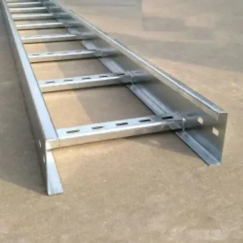
 | Ladder Type Cable Tray Product Description Vickram Engineering is a leading manufacturer and supplier of premium-quality Ladder Type Cable Trays designed for supporting and... View product → |
 | Galvanized Cable Tray Vickram Engineering's Galvanized Cable Tray is engineered to provide a strong, reliable, and corrosion-resistant cable support system for industrial,... View product → |
Cable Trays The GI Bolt Nut Type Cable Tray is a robust and dependable cable management solution designed for safe routing and support of electrical,... View product → |
 | Aluminum Cable Raceway By Vickram Engineering Aluminum Cable Raceway from Vickram Engineering is designed to provide a safe, organized, and durable cable management... View product → |