An MS tray is not defined by a catalogue width or the letters “MS” alone: you must specify its steel, finish, load, support span, cable arrangement and site exposure. By the end, you will be able to compare tray materials, calculate a defensible width, write an enquiry and inspect the delivered system before installation.
Key takeaways
- State the steel grade, finish, coating thickness and fabrication method on every enquiry.
- Calculate tray width from cable diameter, fill allowance and future capacity.
- Match ladder, perforated or solid-bottom trays to cable type and installation conditions.
- Check dimensions, coating coverage, edges, fasteners and delivery documents before acceptance.
What MS Cable Tray Means—and How It Compares with GI, HDG and Aluminium
An MS electrical cable tray is a cable-support channel fabricated from mild steel; “MS” identifies the base metal, not its corrosion protection. Specify whether it is bare, painted, powder-coated, pre-galvanized, or hot-dip galvanized after fabrication.
| Option | What it means | Best fit in Bengaluru |
|---|---|---|
| Bare MS | Mild steel without a protective coating | Temporary indoor use only; rust develops quickly with moisture |
| Painted or powder-coated MS | Mild steel protected by a bonded finish | Dry factory interiors and utility rooms; repair damaged coating |
| Pre-galvanized steel | Zinc-coated sheet formed after coating | Indoor routes and protected areas with limited cutting and site damage |
| Hot-dip galvanized steel | Fabricated steel immersed in molten zinc after fabrication | Rooftops, outdoor runs, damp plants and monsoon-exposed routes |
| Aluminium | Lightweight corrosion-resistant metal | Weight-sensitive structures or corrosive areas; check strength and galvanic contact |
The practical rule for ms electrical cable tray for basics in bengaluru is simple: choose coated MS for dry interiors and post-fabrication HDG for exposed or damp routes. Ask for the coating standard and evidence; IS 4759 covers hot-dip zinc coatings on fabricated iron and steel articles.
IEC 61537 addresses tray-system performance, but it does not choose your width, thickness, load or span.
Your enquiry should request the dimensional drawing, material thickness or grade, finish, coating records, load/span data, joint details, supports and inspection documents. Confirm splice bonding and continuity arrangements; do not assume the tray is the protective conductor. A catalogue width and metre price cannot prove two quotations are equivalent.
The Industrial Cable Tray Specifications to Put on Every Enquiry
A catalogue width and per-metre price do not make two quotations technically comparable. Put these industrial cable tray specifications on the enquiry, then require the same evidence from every supplier.
- Tray form, width, side-rail height, depth, perforation pattern, sheet thickness and straight-section length.
- Material grade, finish, fastener type, joint plates, bends, tees, reducers, covers and support hardware.
- Allowable working load in kg/m at the stated support span, including the test method and deflection limit.
- Dimensional drawing, bill of materials, joint details, support recommendations and cable-fill basis.
| Quotation item | State on the enquiry | Evidence to compare |
|---|---|---|
| Material and finish | MS grade; bare, painted, powder-coated, pre-galvanized or HDG after fabrication | Material certificate, coating declaration and coating inspection record |
| Load and span | Working load, support spacing, deflection limit and tray width | Load-span table or test report, not an unsupported rating |
| Joints and supports | Joint type, splice position, hanger or bracket arrangement and fastener grade | Assembly drawing and installation detail |
| Standard and inspection | IEC 61537 performance basis; inspection and test documents | Declaration or test report, dimensional inspection record and coating report |
Ask whether “GI” means pre-galvanized sheet or post-fabrication hot-dip galvanizing. For fabricated steel, request coating evidence against IS 4759. IEC 61537 addresses mechanical performance, electrical continuity, flame propagation and corrosion classification; it does not choose your width, thickness, span or load. Keep those project values explicit.
Size the Tray from the Cable Schedule, Not the Catalogue
Start with the cable schedule’s actual outside diameters, not the tray catalogue’s standard widths. A straight-run calculation that ignores a direction change can leave too little room for the cable’s minimum bending radius at an elbow or vertical riser.
Calculate usable width as: sum of cable outside diameters + required separation between cables + planned spare width. State spare capacity as a percentage or as a number of future circuits; do not hide it in an oversized tray.
Use these inputs for each route:
- Outside diameter and mass per metre for every cable
- Required separation for power, control and communication cables
- Minimum bending radius at route changes
- Future cable percentage or reserved circuits
Select tray depth from the tallest cable and its required clearance. For multiple layers, add the height of each layer and the clearance between layers. Check the deepest point at vertical changes, because a tray that fits the straight run can restrict cable bending at the riser.
Calculate working load in kg/m from the installed cable mass, future cable mass and tray system weight. Add covers, dividers and other distributed accessories, then identify any permitted concentrated load separately. Do not compare load ratings without the same support span and deflection limit.
Choose support spacing from the supplier’s load-versus-span table, using the calculated working load and the longest route segment. Check support locations at joints, bends and vertical transitions against the supplier’s installation detail. Recalculate the load and span if spare capacity changes.
Choose Tray Form and Finish for Cables and Bengaluru Site Conditions
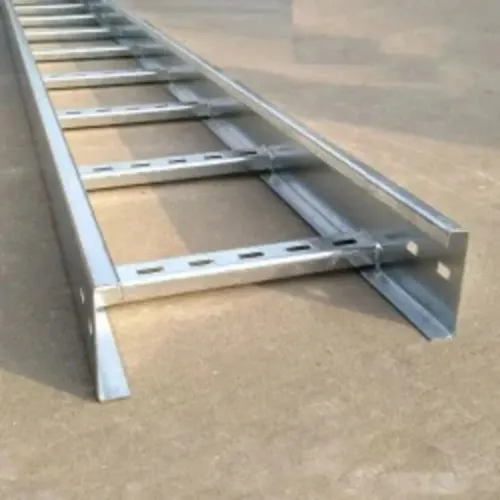
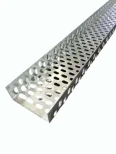
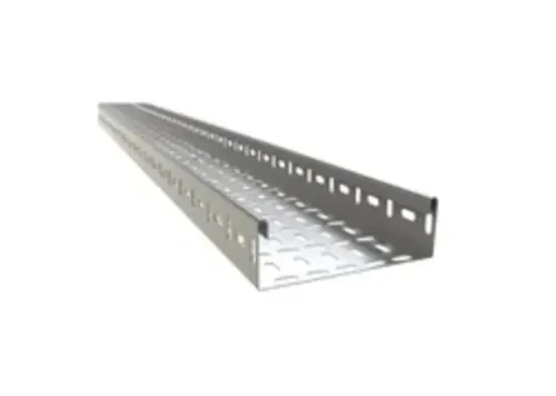
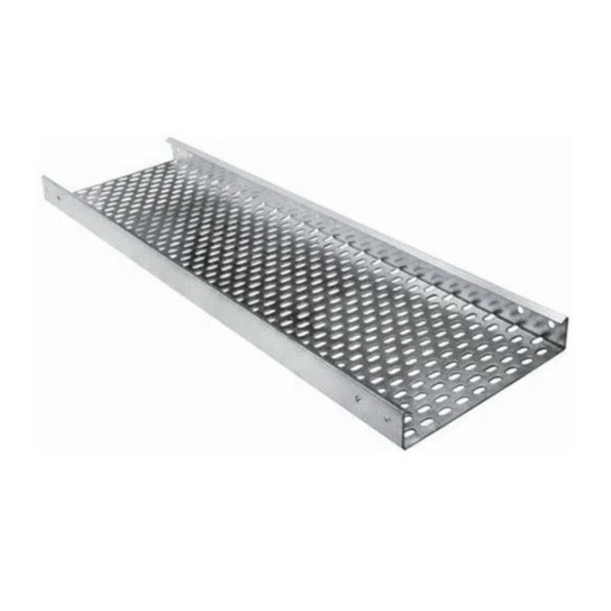
Select ladder tray for large power cables that need ventilation, water drainage and regular cleating. Choose perforated tray for smaller power, control or instrumentation cables needing continuous support. Use solid-bottom tray where dust, falling debris or cable containment matters more than heat dissipation, but provide drainage holes or a slope in wet areas.
| Option | Best use | Main limitation |
|---|---|---|
| Ladder | Heavy, large-diameter power cables; frequent cleats and good airflow | Smaller cables need additional support or ties |
| Perforated | Mixed power, control and instrumentation cables | Less airflow and drainage than ladder |
| Solid-bottom | Small cables exposed to dust, debris or unsupported spans | Traps heat, water and contaminants without drainage |
Do not treat Bengaluru as one corrosion environment. A dry indoor electrical room differs from an open roof, wastewater plant or area exposed to acid, alkali, solvent or chemical fumes.
Select bare or painted MS only for controlled indoor conditions; specify galvanizing or another proven protective system for moisture, and obtain chemical-compatibility evidence before placing trays near process fumes.
Dust favours a cover or solid bottom, but accumulated dust increases heat retention and cleaning effort. For electromagnetic compatibility, bond tray sections across every joint, connect the metallic system to the project earthing scheme, and separate power, control, instrumentation and data cables.
Vickram Engineering can be asked to show joint-bonding details and support recommendations in the quotation, not just a per-metre price.
Related products
 | Galvanized Cable Tray Vickram Engineering's Galvanized Cable Tray is engineered to provide a strong, reliable, and corrosion-resistant cable support system for industrial,... View product → |
 | Ladder Type Cable Tray Product Description Vickram Engineering is a leading manufacturer and supplier of premium-quality Ladder Type Cable Trays designed for supporting and... View product → |
Verify the Quotation and Inspect the Delivered Tray
Confirm the finish in writing before comparing prices: “GI” alone does not tell you whether the tray is pre-galvanized or hot-dip galvanized after fabrication. Ask an electrical cable tray distributor in Bengaluru for the dimensional drawing, bill of materials, material thickness, coating specification and coating-quality documents.
| Finish | How to identify it | Evidence to request |
|---|---|---|
| Bare MS | Exposed steel has no zinc coating; rust can begin at cut edges | Material certificate and paint or coating specification, if any |
| Pre-galvanized | Zinc-coated sheet is formed, cut, drilled or welded; exposed edges and fabrication marks can show unprotected steel | Sheet coating certificate and stated zinc coating designation |
| Post-fabrication HDG | The completed tray, including fabricated edges and holes, is dipped after fabrication | Hot-dip galvanizing certificate, batch reference and compliance with IS 4759 |
1. Match the quotation against the purchase order and approved drawing. Check tray width, side-rail height, thickness, straight-section length, perforation, finish, support span, load rating and joint design.
2. Count every accessory in the bill of materials: bends, tees, reducers, covers, supports, splice plates, bolts and earthing jumpers. Missing fittings can stop installation even when the metre price looks correct.
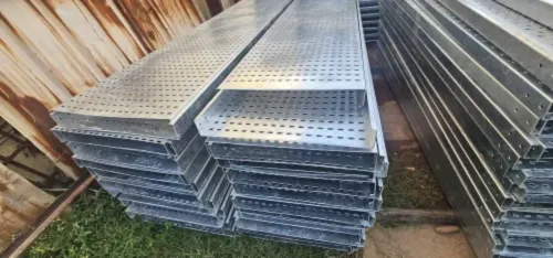
3. Measure delivered sections with a vernier or steel rule and inspect dents, sharp burrs, blocked holes, weld defects and coating damage. Record each discrepancy with photographs, section numbers and the delivery note.
4. Request load/span data and test or inspection records. IEC 61537 supports system evaluation, but it does not confirm your project’s required width, load or support spacing.
Frequently asked questions
What does MS mean in an electrical cable tray?
MS means mild steel, the tray’s base metal. It does not identify the corrosion protection, which could be bare, painted, powder-coated, pre-galvanized or hot-dip galvanized after fabrication.
What industrial cable tray specifications should you put on an enquiry?
State the tray type, width, side-rail height, thickness, material grade, finish, coating requirement, load requirement, splice plates, bends, tees, reducers, supports and required quantities.
How do you size an MS cable tray from a cable schedule?
Use the cable schedule to total cable diameters, add the required separation and spare capacity, then select a tray width and load rating that supports the installed cables without overcrowding.
How do MS, GI, HDG and aluminium cable trays differ?
MS describes mild steel. GI usually identifies zinc-coated steel, while HDG means hot-dip galvanizing; aluminium is a different base metal. Compare corrosion resistance, weight, strength, earthing continuity, finish and site conditions.
What should you inspect when an MS cable tray arrives?
Check the ordered dimensions, steel thickness, straightness, holes, bends, edges, coating coverage, weld quality, fasteners, accessories, quantity and documents such as the material or coating certificate.
Related products
Horizontal Cable Tray Bend Vickram Engineering's Horizontal Cable Tray Bend is a precision-engineered cable management accessory designed to facilitate smooth directional... View product → |
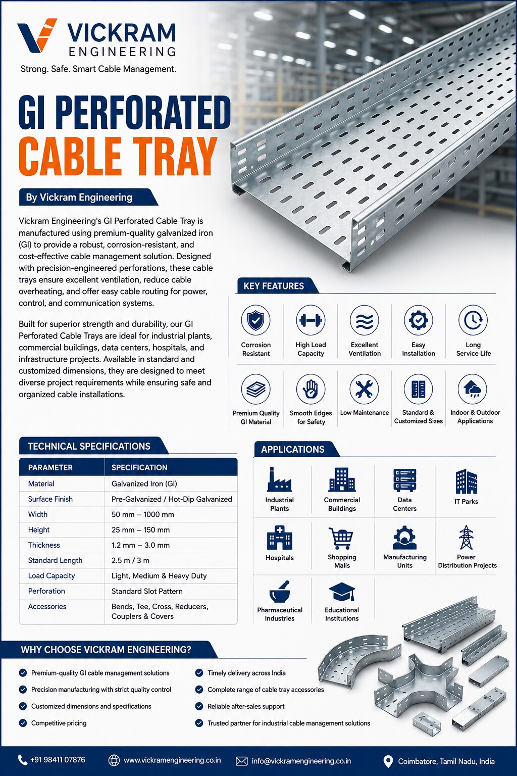 | GI Perforated Cable Tray Vickram Engineering's GI Perforated Cable Tray is manufactured using premium-quality galvanized iron (GI) to provide a robust, corrosion-resistant,... View product → |
Cable Trays The GI Bolt Nut Type Cable Tray is a robust and dependable cable management solution designed for safe routing and support of electrical,... View product → |
Keywords