Fix the route from equipment connection points outward, then test every bend, elevation change, crossing and termination against the cable schedule and the site. By the end, you will have a practical method for choosing tray directions, coordinating congested areas and issuing an installation package that accounts for Bengaluru weather, maintenance access and future cables.
Key takeaways
- Start routing from equipment connection points and maintenance clearances.
- Use straight tray runs with planned bends instead of forced sharp turns.
- Size tray width and bend radius from the complete cable list.
- Coordinate fire boundaries, plant zones and site conditions before installation.
Start at equipment connections, not at the shortest centreline
Fix the route from equipment connection points outward, not from the shortest centreline. Wire mesh cable tray direction planning in Bengaluru starts with connection geometry: a short route becomes a poor route if it creates tight bends, blocks maintenance access or crosses incompatible plant zones.
Collect this information before choosing the tray direction:
1. Record every cable’s origin, destination, outside diameter, minimum bend radius, termination method and allowable pulling tension. Include spare cables and future circuits.
2. Mark each circuit’s category: power, control, instrumentation, communications or intrinsically safe. Confirm required separation, EMC controls, voltage grouping and hazardous-area restrictions for the project.
3. Locate equipment glands, marshalling cabinets, junction boxes, panels and motor terminals. Note entry direction, removable covers, gland-plate space, drip-loop needs and the clearance required to withdraw or replace equipment.
4. Survey the actual plant, not only old drawings. Record beams, slabs, columns, structural steel, fire piping, HVAC, drainage, access roads, crane paths, underground services and maintenance-removal routes.
5. Mark fire-rated walls, process areas, hot surfaces, chemical exposure and zones where a tray crossing would obstruct operations. A geometrically efficient route can fail when it enters the wrong fire or process zone.
6. For outdoor or semi-outdoor runs, record roof drains, parapets, wall penetrations and low pockets where rainwater, mud or debris could collect. Wire mesh drains water, but it does not seal glands or penetrations; specify drip loops and weatherproof interfaces.
Use this information in industrial cable route planning before drawing straight runs, risers or drops. Then check the selected tray system’s tested load/span data, fitting compatibility and required future capacity.
Build the route from straight runs and controlled direction changes
Lay out horizontal cable runs as straight sections joined by controlled changes, then treat each elevation change and equipment entry as its own route element. Start at the connection point and work outward; a shorter centreline is a poor choice if it creates tight bends, inaccessible pulling points or an overloaded fitting.
Set out each element in the route schedule:
- Straight run: show length, tray width, support points and the reserved spare capacity.
- Horizontal bend: use a compatible factory elbow and record its angle and cable bend-radius requirement.
- Riser or drop: show the vertical transition, support method and access for pulling and maintenance.
- Tee, cross or reducer: confirm the fitting capacity and keep branches accessible for future cables.
- Termination: detail the final tray support, gland plate, entry seal and cable restraint.
Good wire mesh cable tray planning in Bengaluru uses the manufacturer’s fittings wherever possible. Improvised field bends can distort the mesh, damage its finish, reduce load capacity and leave sharp edges that abrade cable jackets.
At every bend, use the largest cable’s manufacturer-specified minimum installation radius, not the radius printed on the tray elbow. Do not force a cable around a fitting that passes the tray geometry but fails the cable requirement.
Keep low pockets out of outdoor routes so rainwater, mud and debris cannot collect. Coordinate elevations with roof drains, parapets and wall penetrations; add drip loops and weather seals because mesh drainage does not seal a building entry.
Reserve width, pulling space and support capacity in the design basis. Keep circuits separated where voltage, noise sensitivity or hazardous-area rules require it; a metallic tray alone does not provide segregation.
Size width, bend radius, supports and segregation from the actual cable list
Use the actual cable schedule as the sizing input, not an assumed tray width. Record each cable’s outside diameter, mass, minimum installation bend radius, origin, destination, segregation class and pulling direction before fixing the route.
Calculate the tray from these checks:
- Width: add the cable outside diameters within each required group, then reserve a stated width for future cables and pulling access. Do not consume that reserve during installation.
- Depth: select a depth that holds the planned cable layers without crushing lower cables, then confirm the manufacturer’s load table for that arrangement.
- Bend radius: use the cable manufacturer’s minimum installation radius. Show the largest radius at every elbow, riser and drop; the fitting radius alone is not proof of compliance.
- Supports: verify span, bracket capacity and fixing locations against the loaded tray, fittings and vertical cable weight. Add support near direction changes and riser transitions.
- Protection: reject low pockets that collect rainwater or debris, and detail sealed penetrations, drip loops and equipment entries separately from the tray.
Assign circuits to the required separation arrangement:
- Power circuits
- Control and instrumentation circuits
- Communications and data circuits
- Intrinsically safe circuits
A metallic wire mesh tray does not remove EMC or hazardous-area segregation duties. Use separate trays or approved compartments where the project requirements demand them.
For industrial cable route planning, check that every bend, tee, reducer and riser uses a compatible fitting without sharp edges or improvised field bends. This is the core of wire mesh cable tray direction planning in Bengaluru: confirm capacity, separation, support and cable protection at every route segment, not only on the straight run.
Coordinate sections, fire boundaries and Bengaluru site conditions before installation
Release the route only after building, plant and environmental constraints are fixed against verified site conditions. Wire mesh cable tray planning in Bengaluru must follow equipment connection points outward, while industrial cable route planning records each cable’s destination, bend radius, segregation class, maintenance access and future spare capacity.
Power, control, instrumentation, communications and intrinsically safe circuits need separate trays or compartments when voltage, noise sensitivity, cable construction, hazardous-area classification or the project standard requires it. A metallic tray does not remove segregation obligations.
Resolve these site interfaces before issuing construction drawings:
- Fire-rated walls and floors: define each penetration, tested fire-stopping system, required rating and a documented method for sealing future cable additions.
- Roofs and outdoor routes: avoid low pockets that retain rainwater, mud or debris; coordinate elevations with roof drains, parapets, wall sleeves and drip loops.
- Plant access: preserve crane paths, equipment-removal routes, doors, walkways and maintenance clearance.
- Existing services: verify underground utilities, structural steel, pipe racks, fire piping, HVAC, drainage and live cables on site rather than trusting old drawings.
| Constraint | Confirm before release | Consequence if missed |
|---|---|---|
| Fire boundary | Opening size, fire rating and compatible seal | Compartmentation fails |
| Weather interface | Drainage, penetration seal and equipment-entry detail | Water reaches cables or glands |
| Plant congestion | Structural, piping, HVAC and removal clearances | Tray clashes or blocks maintenance |
At columns, risers, transformer rooms and crossings, issue plan, elevation and section views. These expose inaccessible couplers, inadequate vertical clearance and bends that cannot achieve the cable’s minimum radius.
Issue a constructible tray package and verify the selected system
Release the route only after the package shows how every tray section is built, supported, accessed and terminated. A cable tray layout contractor in Bengaluru should issue coordinated plan drawings, elevations and sections, with enlarged details at columns, pipe racks, risers, transformer rooms, wall penetrations and plant crossings.
1. Mark each straight run, horizontal bend, tee, cross, reducer, vertical offset, riser, drop and termination with a unique tag. Show tray width, depth, elevation, support type and spacing, coupler position, bend radius, clearances and fire-sealing details.
2. Attach a cable schedule showing origin, destination, outside diameter, minimum bend radius, voltage or signal class, segregation requirement, installed length and future spare allowance. Identify separate trays or compartments for power, control, instrumentation, communications and intrinsically safe circuits where the project requires them.
3. Add sections that prove cables can enter equipment without exceeding bend radius and that couplers, glands and maintenance paths remain reachable. Show roof drainage, parapets, drip loops, penetration seals and low points on outdoor or semi-outdoor routes.
4. Verify the latest site survey against structural steel, beams, HVAC, fire piping, drainage, underground services, crane paths, access roads and equipment-removal routes. Record each unresolved clash on the drawing register before issue for construction.
Ask Vickram Engineering or another supplier to confirm compatible mesh fittings, finish, load rating, allowable support span, edge protection, couplers and fire or corrosion suitability against the issued schedule. Reject improvised field bends unless the supplier approves the method in writing. This is wire mesh cable tray planning in Bengaluru, not a centreline drawing exercise.
Related products
Horizontal Cable Tray Bend Vickram Engineering's Horizontal Cable Tray Bend is a precision-engineered cable management accessory designed to facilitate smooth directional... View product → |
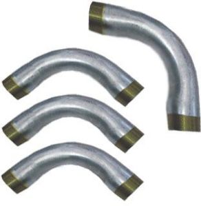 | Fittings Vickram Engineering is a trusted manufacturer and supplier of high-quality cable trays designed for efficient cable management in industrial,... View product → |
Frequently asked questions
Where should wire mesh cable tray route planning start?
Start at equipment connection points and work outward. Check cable entry direction, bend space, gland positions and maintenance access before selecting the centreline.
How should you plan tray direction changes?
Build routes from straight runs and controlled direction changes. Use suitable bends, tees and crossovers instead of forcing cables around sharp corners.
What information is needed to size a wire mesh cable tray?
Use the actual cable list, including cable diameters, quantities, separation requirements, bend radii, spare capacity and support spacing.
What site issues must Bengaluru contractors coordinate before installation?
Coordinate tray sections with equipment layouts, fire-rated boundaries, plant zones, ceiling constraints, drainage, access routes and local site conditions before fabrication.
Keywords